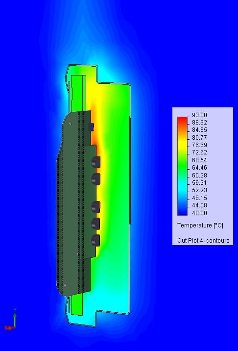
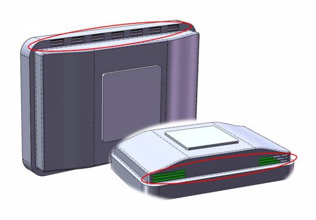
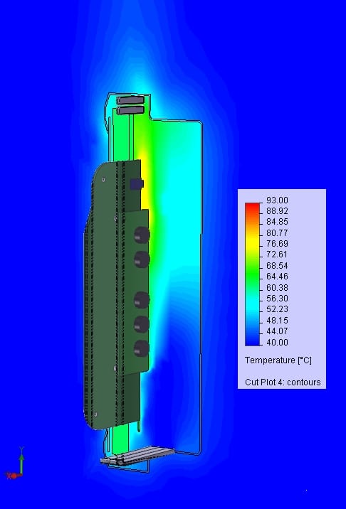
Flow simulation evaluates cooling methods

1354_ffa70edf

He doesn’t need much thinking to answer the question.

– It’s heat dissipation that’s the bigger challenge when it comes to my responsibilities in our embedded projects, says Guido Kats, Mechanical Engineer at Hectronic.

 He uses SolidWorks Flow Simulation, integrated in the 3D CAD environment, to simulate air flow, temperatures and hot spots. But the actual design is always based on personal experiences.

– The flow simulation tool is important, for sure. It enables us to show to customers that the concept we are offering is working.

Step 1 – Creating a model

The result from the flow simulation indicates if the cooling of the design is sufficient based on a model. The shape and material of the enclosure, the size of inlets and outlets and consumption and placement of and heat dissipating components are all input to the model.

Too many details and the computer is overloaded by massive calculations. Not enough details and the result will be inaccurated or even incorrect. The picture shows components and their respective power consumptions placed in the model of the system in question.

1353_e643d0ef

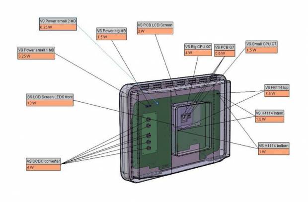
VS: Volume Source. Objects emitting heat from a solid body in all directions.
SS: Surface Source. Objects emitting heat from a  surface.

Step 2 – Performing the flow simulation

The picture shows a section of the system with temperature regions, gradients and hot spots. Some of the components reach the maximum allowed temperature of the system, nearly 90°C. The specifications are consulted to evaluate the temperature of the components individually. In this case a DC/DC converter for the LED LCD exceeded its upper temperature limit of +85°C suggesting that the design needed modifications.

1355_e643d0ef

Step 3 – Design modifications to solve the heat problem

In general, gap pads on critical components may be sufficient cooling for embedded systems in the low power segment, around 5W, even though the enclosure is closed.

– If there’s some kind of air flow inside the box it may be good enough to take the heat away.

If not, as in this case, there are a handful of additional heat dissipation methods: Heat dissipation through a metallic enclosure, heat sinks on components or on the exterior of the box, heat pipes for heat distribution, inlets and outlets in the enclosure to increase the air flow or a fan.

Cooling with a fan is sometimes necessary, for example to design a powerful and yet compact system, but there are drawbacks.

– It makes noise. It can break down. Airflow comes out and dirty air is forced into the enclosure.

The suggested alteration in the example was to introduce holes in the cover. That would enable air to flow in through the bottom of the enclosure, through the interior and electronics and out on the upper side distributing heat for increased cooling.

1357_e643d0ef

Step 4 – Flow simulation to show the effect

The picture below shows the result from the flow simulation to evaluate heat dissipation after the modifications have been made.

1356_e643d0ef

The result from the second flow simulation shows a temperature decrease of approximately 10°C on one the critical components, the DC/DC converter. Thus the design modification proved sufficient to solve the problem.

This was a brief example from the work of Mechanical Engineer Guido Kats involving heat dissipation issues. Other duties involve for example EMC protection, protection against solid foreign objects or water (IP-classification), shock and vibration, but that’s another story.

More questions about flow simulation? Contact Hectronic!

  • Subscribe to news

Required

Get contacted

We get back to you as soon as possible

Required
This site is protected by reCAPTCHA and the Google Privacy Policy and Terms of Service apply.